")

-
Updating the Control Box antenna rotor
In the February 2013 RadioKit Electronics issue, on p. 9-13, was published my article on a control box microprocessor. Normally between sending a piece and its publication a substantial period of time passes. Fortunately, this is a good omen for us experimenters, meaning that despite the difficulties in obtaining the materials and in, smaller and smaller devices, there are many ideas and innumerable proposed projects.
-
Often between the time when the article is sent and its publication, the project continues to evolve, both in the correction of hardware or software failures, than in the development of new functions. Cbox is no exception and in recent months has seen software revisions and management developments. In these pages the features, already abundantly illustrated in the journal above mentioned, will not be repeated but the changes and developments that the project has had in the interim time will be highlighted.
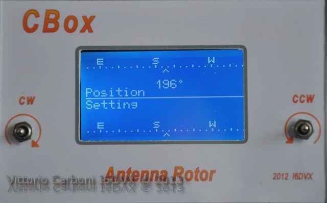
Graphic Display
Lately, especially in purchases from China, it’s easy to find graphic 128 x 64 displays fitted with a chip as a controller ST7920, instead of the previous KS0108. Unfortunately they are not compatible, and without a clear statement is difficult to understand which is the device we face. The physical dimensions are identical, and this does not help. Also, just to complicate things, while mounting the controller, not all graphic displays have the same pinout.
In our case the card with the new controller ST7920 has 4 different pin than the card that mounts KS0108. The differences in pin are highlighted in the table.KS0108 # Pin Symbol Function 15 CS1 Select Col. 1..64 16 CS2 Select Col.65..128 17 RST Reset Signal 18 Vout Output Voltage ST7920 # Pin Symbol Function 15 PSB H: Parallel L: Serial 16 NC -- 17 RST Reset Signal 18 NC --
In order to use either one or the other, I have changed and recompiled the library: available on the website for download, there are two different firmware:- CBox_v1.41.hex for the controller KS0108,
- CBoxST_v1.41.hex for the controller ST7920.
New Features
New features have been added to the firmware. Now you can delete the control of current drawn by the motor. Holding down the rotate counter-clockwise (CCW) button during power on, you enter a setup that allows you to change the flag that enables or disables control over the maximum current drawn by the motor. The state of the flag is stored in EEPROM so that it is not necessary to repeat the process each time. The starting setup is prompted automatically when first turned on, or whenever is necessary, holding down both turning on buttons. Having the ability to connect to the Control Box via RS232, the number of commands has been expanded. Now, in addition to the subsets of 3 commands of protocol GS232, there are 4 other commands that allow you to read and modify the parameters stored in the EEPROM of the microcontroller for easier management. So in addition to confirm the possibility of management of the Control Box with programs similar to WinMix, a small software has been developed, called "CBOX Commander". It operates in a Windows environment, its prominent use is for verification, debugging and setting of parameters in eeprom. Use of the software is extremely simple, as well as the user interface is spartan. 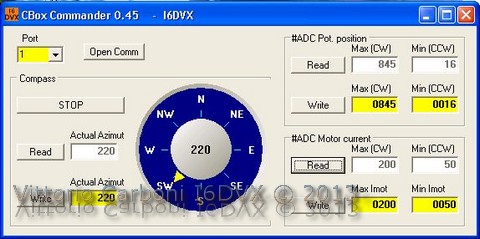
Just indicating the number of the serial port and at once it’s connected. With 1 second intervals all the parameters of the Control Box are read and displayed. These parameters can be modified through the windows with a yellow background. It take just a few minutes to familiarize yourself with the program.
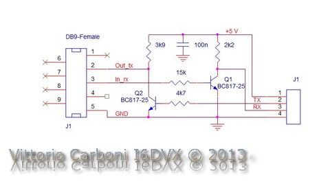
- The serial interface can be realized with one of the many chip converters level (TTL-RS232), or more simply with two transistors. In this way it’s not achieved bipolar RS232 protocol, but it works perfectly for distances of several meters. In the two prototypes, in one case we used a MAX232 dedicated chip; for the external connection, instead of the classic DB9 connector, we used a 3.5 mm stereo connector. For the second prototype we used two transistors, with the components in smd except connectors. In this case the external connector is the classic DB9. The two interfaces work perfectly, but the second is undoubtedly more simple and economic.
Conclusions
Another demonstration of how to update obsolete or non-functional Control Boxes. The new Control Box has been running for almost a year and never gave any problems. As a possible future expansion, you might consider adding to the Control Box also management a brake, if present.
Have fun.
Related Topics- Pubblications: Control Box di oggi per rotori di ieri
- Documents: CBox EN
- Firmware: CBox & CBoxST v1.41
- Software: CBox Commander v0.45
- PCB: CBox_PCB