")


Two Tone Generation
In the measurements of linearity of amplifiers and / or transmitters, a small little tool is used, its function is to generate two sinusoidal audio signals. The value of these two frequencies is not binding, what’s important is that they are both in the clear band of the transmitter filter; generally, this range is between 300 Hz and 3000 Hz for SSB emissions. Furthermore, it is appropriate that these frequencies differ between them as much as possible.
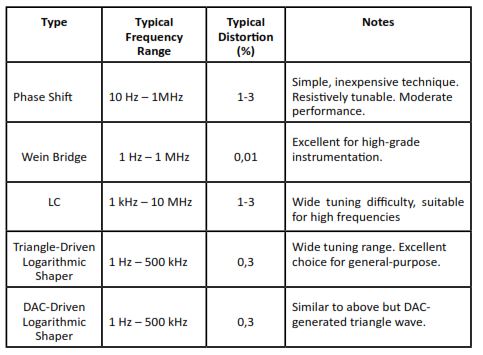
Having to take measurements of distortion, it is good that the signals are generated as pure as possible, with low harmonic content, so as not to generate artifacts that can bring to wrong conclusions in the analysis of the results. Consequently, it’s necessary to gauge with forethought what type of signal generation is more suitable for one’s purpose. The following Table 1 is taken from an Application Note by Texas Instruments1, and it shows the characteristics, in particular the typical distortion, of different types of oscillators. From data extracts from the table, we are going to take into consideration only two possible types: the phase shift oscillator and the Wein bridge oscillator.
Phase Shift Oscillator
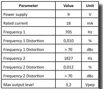
Phase shift oscillator is among the most widely used type in the realization of two-tone generator. Economic and safe operation allows to realize a discreet generator. A quick search on the Internet shows very similar interesting projects, such as Hendricks Two Tone Generator2, Two Tone Generation TTG13 of PrecisionRF. On the basis of such schemes a few prototypes have been made. The overall electric scheme is visible in Figure 1. Please refer to the substantial amount of material available on the Internet for theoretical study of the operation of this type of oscillator. The scheme is classic, for both tones there is the possibility to adjust, through semi-fixed potentiometers (R13, R28), the value of the frequency generated, even if it is not of primary importance. It’s possible to balance the amplitudes of the two signals through R16. The integrated circuit U1, is the amplifier of BF and the overall level of the signals is controlled by R17. The two signals can be generated individually or jointly, the switches S1 and S2 is entrusted with this task. A note on the integrated circuit amplifier, U1 LM386: it seems that the plastic version DIL (Dual In Line) container is longer manufactured but is available only the surface mount version. That’s why in the first prototype, for the realization of the PCB, seen that for such integrated was used the version DIL as footprint, and since failing to find on the market such circuit, I resorted to an DIL SMD adapter mounting the SMD version. The Table 2 shows the main characteristics measured on the first phase shift oscillator.
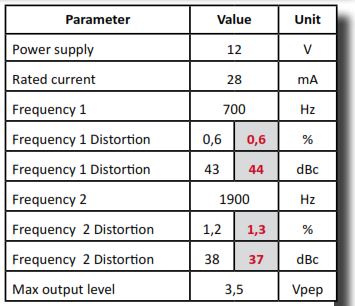
Please note that the measurement of total harmonic distortion (THD), both in percentage and in dBc, was implemented both with Marconi Instrument TF-2331 distorsion meter and also with different software tools via PC. In particular, SpectraPlus – SC4 was used, the software is not free but fully functional for 30 days. Alternatively you can also used Visual Analyzer5, a completely free software. All the instruments used, both hardware and software, have provided consistent results
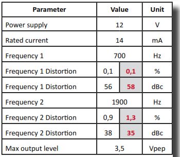
and always comparable. The main features of the first phase shift generator prototype are gathered in Table 2, the following Table 3 reports the measurements relating to the second phase shift generator prototype. The THD distortion values, shown in the white background cells of the tables were measured with TF-2331, those reported in cells with gray background were measured with software.
Wien Bridge Oscillator
The type of Wien bridge oscillator promises extremely low levels of distortion. Some important considerations: the values of R and C determine the frequency of oscillation. It is good that these four elements have low tolerance (=> 2%). The condition for the circuit swing and for an extremely low distortion is that the gain is equal to 3, then R2 = 2 x R1.
This condition is critical, in fact, to ensure the trigger is necessary that the report be R2> 2 x R1 is verified, but in this condition the distortion is high. It’s therefore necessary to introduce an artifice that allows to have an initially gain greater than 3, such to ensure the trigger. After oscillation began, gain must be reduced in order to obtain low distortion. Tradition has it that Hewelett-Packard - then Agilent and today Keysight Technologies- luck began precisely with the design of the first instrument: a Wein bridge oscillator for low frequency (HP-200A), wherein the element which ensured the trigger and the subsequent stabilization of the generated signal was a simple light bulb. In fact, the filament of the lamp behaves as a resistor with a positive temperature coefficient. Initially the resistance value of filament is low, then with the passage of modest current through it it increases making the amplitude of the sinusoid and low harmonic distortion stable.
 For further theoretical analysis, see again to the considerable amount of material available on the Internet. The proposed circuit is shown in Figure 9. Also in this case, the diagram is classic. As active element a high speed J–FET input quad operational amplifiers, the TL07,4 is used. The second section, U1B, realizes a virtual mass to half the voltage of power supply, so as to use the voltage of the single battery as dual power, indispensable for the use of the operational amplifier. Thus taking advantage of a section of the operational, otherwise not used, we can save the use of two batteries, vice versa needed to obtain dual power supply. The first and the fourth section, U1A and U1D, are the two oscillators, the last section, U1C, is used as amplifier / separator. The resistors R1 and R2 R7 R8 should be at least 2% tolerance, or better. The pairs of capacitors C1 C2and C4 C5 were selected for their most similar values in between, with the aid of a capacitance meter. The stabilization of the gain is realized with N-channel JFET, J310. The calibration of the two generators is very simple: you adjust the 500 ohm R5 and R11 multi-turn trimmer for the minimum of distortion, using one of the software indicated previously. The results in terms of distortion are visible in Table 4 and are more than flattering. The harmonics levels are below the fundamental frequency of more than 70 dB. It may be useful to recall that dB is a logarithmic unit used to express the ratio of two values, and that 70 dB means that the higher harmonic level, in voltage, is 10,000,000 times smaller of the fundamental. Additional material for the realization of printed circuit boards will soon be made available on the site6.
Good construction.
1- AN-263 Sine Wave Generation Techniques, Texas Instruments, Application Report, SNOA665C–October 1999–Revised April 2013
2- http://www.qrpkits.com/files/ttg_assy_042013.pdf
3- http://preciserf.com/wp-content/uploads/2012/05/datasheet-TTG-1v2.pdf
4- http://external.informer.com/spectraplus.com/
5- http://www.sillanumsoft.org/Italiano/
Related topics:
Two-tone generator, article in PDF |
|
 |
Download |
Two Tone Generator Phase Shift & Wein Bridge: BillOfMaterials, PCB, Schematic, SilkTop. |
|
| |
Download |
http://i6dvx.it/en/lavori-in-corso/generatore-due-toni.html#sigProId69525bbfc2
-
 Fig.1
Fig.1
Fig.1
Fig.1
-
Fig.2
Fig.2
-
Fig.3
Fig.3
-
Fig.4
Fig.4
-
Fig.5
Fig.5
-
Fig.6
Fig.6
-
Fig.7
Fig.7
-
Fig.8
Fig.8
-
Fig.9
Fig.9
-
Fig.10
Fig.10
-
Fig.11
Fig.11
-
Fig.12
Fig.12
-
Fig.13
Fig.13
-
Photo 1
Photo 1
-
Photo 2
Photo 2


http://i6dvx.it/en/lavori-in-corso/generatore-due-toni.html#sigProIdd982560abb