")

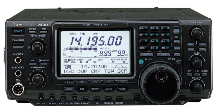 Icom IC-7400: ATU repair
A few months ago my trusty IC-7400, when the automatic tuner attivavo an embedded, it was a tantrum. In the sense that a few times, few, reached the point of minimum VSWR, many times after a tentative agreement, the tuner was disabled..
A quick consultation of the diagrams shows that the boards responsible for the tuner function are two: the Control Unit and the Tuner Unit. The Control Unit has three sensors to read the agreement reached. The first sensor detects the SWR as forward and reflected power. The second sensor detects the phase of the RF signal, the last detects the resistance value of the load applied. A dedicated microprocessor reads the sensors and actuators act directly on the card Tuner Unit. The card Tuner Unit hosts, such as actuators, a series of relays, which in function of the working frequency, switch on or off capacitors and inductors. There are also two variable capacitors 150 pF moved by stepper motors controlled by the microprocessor of the control unit. A clarification: the two variable capacitors (C44, C45) are not shown in the diagram with the symbol of variable capacitors.
FIRST ATTEMPTS TO DIAGNOSIS
To perform the measurements you need to remove the outer cover, side handle included.
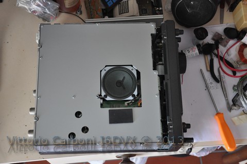
The first steps have been subject to the sensors, then there has been the presence of switching signals on connector J8 on the Control Unit. References are indicated on the truth table shown on the page of the wiring diagram of the Tuner Unit, pattern stretch from Service Manual (S-13811HZ-C2) retrieved on the network. The measurements showed no problems, so the attention is focused on the actuators mounted on the Tuner Unit. To reach the Tuner Unit must be removed from its housing the Control Unit. Removed all connectors are soldered two Rimage and therefore not removable. Removed all the screws to remove the card you need to unsolder the connections to the two connectors (UHF Ant 1 & 2).
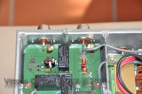
It is easy to remove the pond with a ' sucking pond ' or a desoldering braid , so as to free two scourers mass. Desoldering of the two bridges on the central connector. Now the Control Unit card is free and can be rotated. Inferiorly the Tuner Unit is protected by an additional screen. Remove the last 4 screws finally you can access the Tuner Unit. The card has been removed from its holder, bench was fed with 12 V, and on the connector J5 were simulated micoprocessore signal of put 5 V on each input and verifying the activation of individual relays. Where possible there has been a contact closure relay energized. Although these checks gave no indication as to justify the failure. It is then passed to check the behavior of the two variable capacitors and their actuators. When reassembling and reconnecting the two boards was observed, not without some difficulty, the excursions of the two variable capacitors, noting that the outermost motor, while rotating, had a minor excursion on the other motor. To exclude driving problems, have reversed the connectors of the two motors. The outboard motor maintained a modest hike : finally a good clue!
STEPPING MOTOR
An Internet search of the datasheet of the motor immediately showed the difficulty of finding information. The directions of the plate shows: MP28GA, 12V DC, Mitsubishi. On the manufacturer's website, there is nothing! Some feature has been extrapolated from sites in Chinese and Russian. They found indications of equivalent engines indicated by the letters MP24ZA, ST28, MOTS1. The salient features of the engine should be:
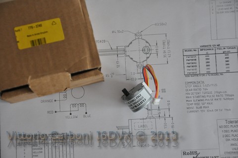
- Voltage 12 V
- Phase 4
- Step-by-step angle 5,625°
- gear ratio 1:64
A motor equivalent has been found and purchased at RS Components 779-3740 code produced by Clif Electronics FMJ7301CH. It also indicates the availability of Future Electronics another engine probably equivalent, under the name 8020-MOTS1.
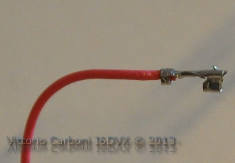
The motor connector has purchased a step smaller than the original, but this is not a problem: it is simple in fact pull the wires from the connector block, with the aid of a pin, and place it on the block of the engine is defective. Properly orienting and re-inserting the wire into the terminal block, the tooth on the terminal hangs. It is a task more complex to explain than to do, the pictures should help.
The replacement motor is not difficult : just loosen the two allen screws in the flexible coupling ( MP8 ) that combines the motor shaft to the variable capacitor .
At this point the motor slips off from the pins ( MP6 ) . Do only attention to the position of the lock ( MP7 ) to be a joke ( counterclockwise ) to capacitor fully closed ( maximum capacity).
For what has been observed , when the equipment , both motors are brought to the top of stroke . This is achieved in a violent way . In fact, since there is no feedback on the position of the motor, this is rotated counterclockwise to a time more than enough ports affiche the capacitor at maximum capacity , even if it was at minimum capacity . Block connettoreCiò is achieved by locking the latch with the MP7 engine. From this moment , the microprocessor knows the position of the motor. This allows to quickly regain agreements already made because the microprocessor stores the position of the previous agreements obtained .
Conclusion
Although not yet explicitly said, the 7400 has returned fully operational. The engine chosen, therefore, proved to be perfectly equivalent to the original. It is believed that the problem was caused by a mechanical stop to the zero position: without any restriction on the power to the motor, probably the gears of the gear ratio you are ruined. I hope these lines may be of help to someone, 73 de I6DVX.
Argomenti correlati
Downloads: Articolo in PDF
Stepping Motor: Data Sheet